Principle of Moments
| Principle of Moments |
|---|
| Principle of Moments states that when an object is at equilibrium, the sum of clockwise moments about any point is equal to the sum of anticlockwise moments about the same point. |
Bodies in Equilibrium
- When an object is in equilibrium (balanced), it is at a steady state of motion where it is either moving at constant velocity or at rest.
| Conditions for Objects to be in Equilibrium |
|---|
The two conditions for an object to be in equilibrium are:
|
| Example 2 |
|---|
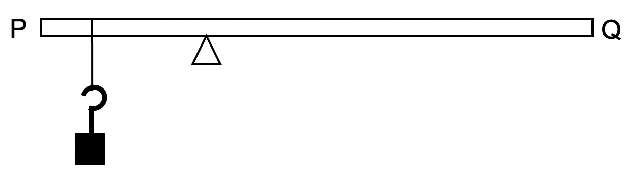
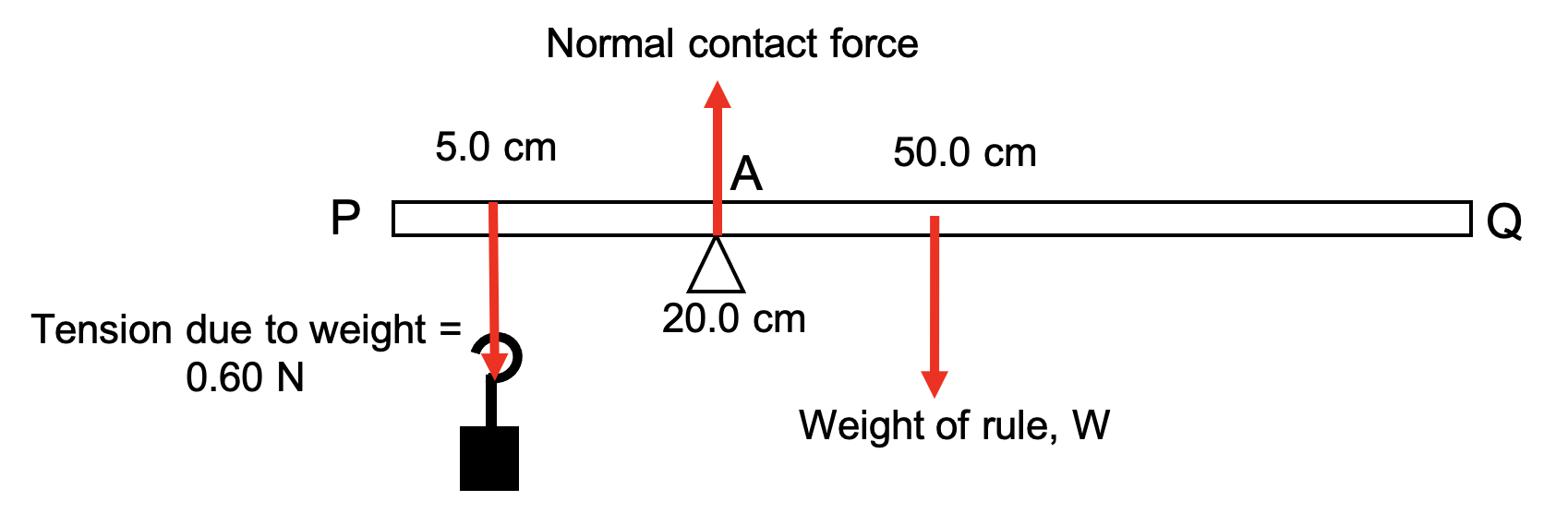
| A uniform metre rule, PQ, pivoted at a point 20.0 cm from end P, is kept horizontal by means of a 60 g mass suspended at 5.0 cm from end P.
(a) On the above diagram, draw and name all the forces acting on the rule.
(b) Calculate the mass of the rule. |
| Example 3 |
|---|
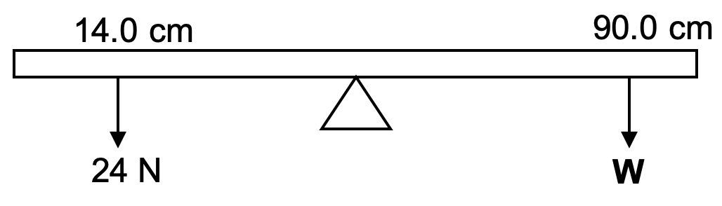
| A uniform metre rule balances horizontally on a pivot at its midpoint when a weight of 24 N is suspended from the 14.0 cm mark and a weight W suspended from the 90.0 cm mark.
(a) Calculate W.
(b) Why is the magnitude of the weight of the ruler not needed to calculate W?
(c) What would happen if the 24 N weight was replaced by a 40 N weight? |
| Example 4 |
|---|
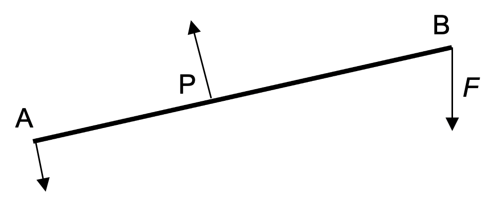
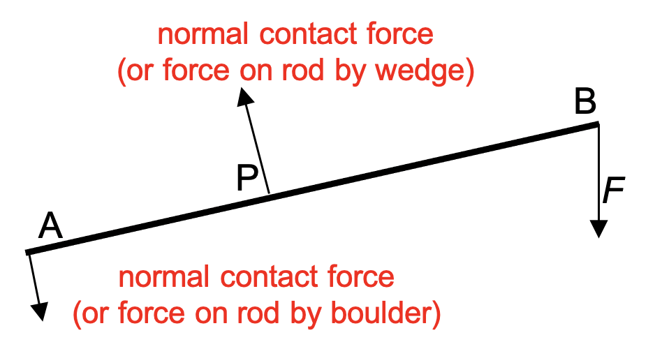
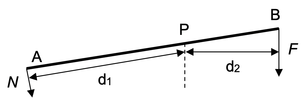
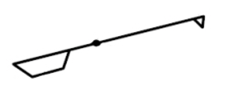
| A stone wedge is placed at P under a long rod AB used as a lever to lift a heavy boulder. A vertical downward force F is applied at B to lift the boulder as shown below. 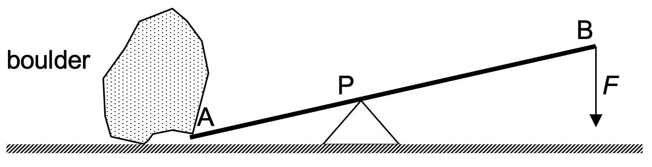 (a) Below is a free-body diagram of the rod. Label the forces at A and P. (a) Below is a free-body diagram of the rod. Label the forces at A and P.
(b) State and explain how the force F needed may change if the position P of the stone wedge is changed. |
| Example 5 |
|---|
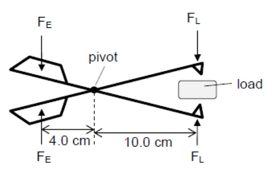
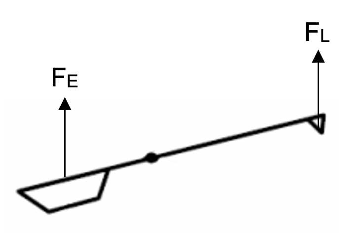
| A pair of tongs can be used to pick up a load. The force FE is applied at the handle to exert a force FL on the load as shown below.
(b) Write down a relationship between FE and FL for the position of the tongs shown above.
(c) State and explain how the force FL on the load would change if the hinge (pivot) of the tongs is nearer to the handle. |
| Example |
|---|
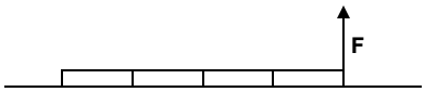
| A 1 m long uniform beam of mass 2 kg is being lifted by a vertical force, F, at the 100 cm mark.
What is the minimum force, F, that will lift the beam? |
| Example 3 |
|---|
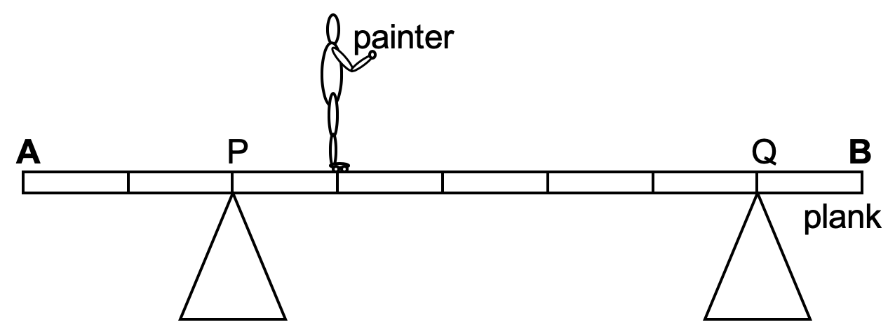
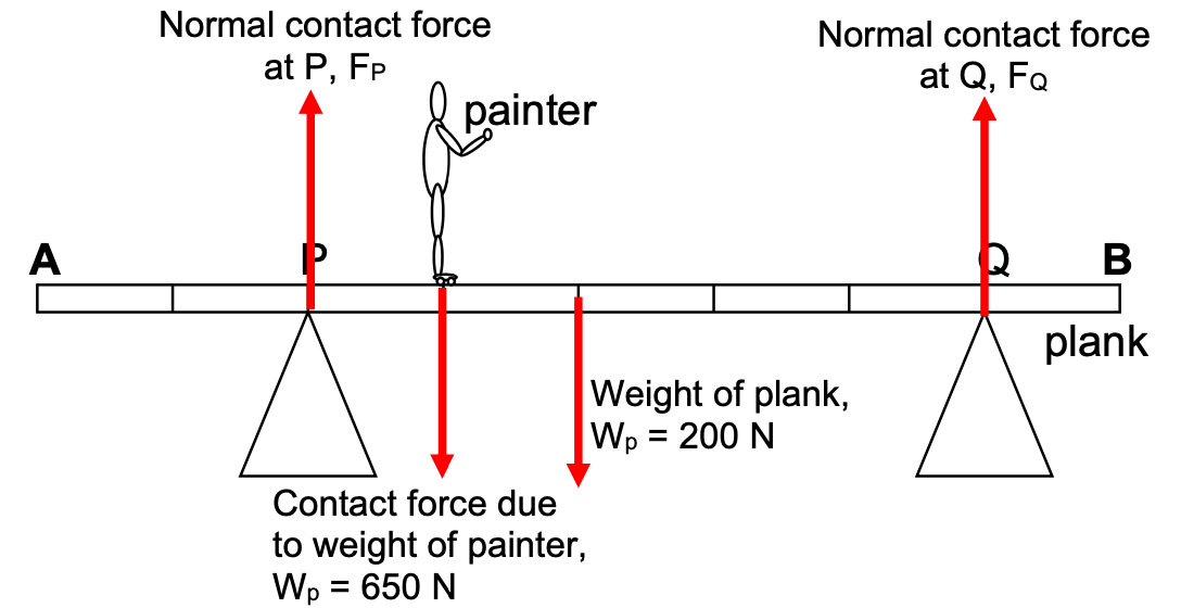
| A painter of weight 650 N sets up an 8.0 m plank as shown to reach the top of a wall he is painting. The plank is uniform and weighs 200 N. The painter is standing 3.0 m from end A as shown.
(a) Mark and label all the forces acting on the plank.
(b) Calculate the force at the support P acting on the plank.
(c) Calculate the force at the support Q acting on the plank.
(d) How close to A can the painter get before the plank topples? |
| Example 4 |
|---|
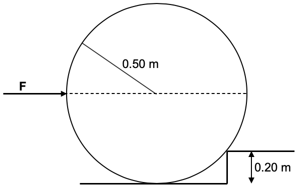
| A ball of uniform density, radius 0.50 m and mass 2.0 kg, is resting against a step of height 0.20 m.
A horizontal force, F, is applied to the ball at the midpoint as shown below.
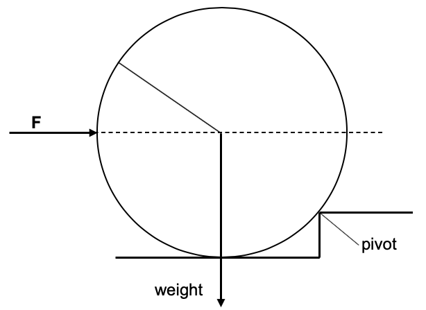
Firstly, consider that in order to roll the ball up the slope we need to produce a moment equal to (or greater than) that produced by the weight of the ball. Also identify the pivot point (the point about which the ball will rotate).
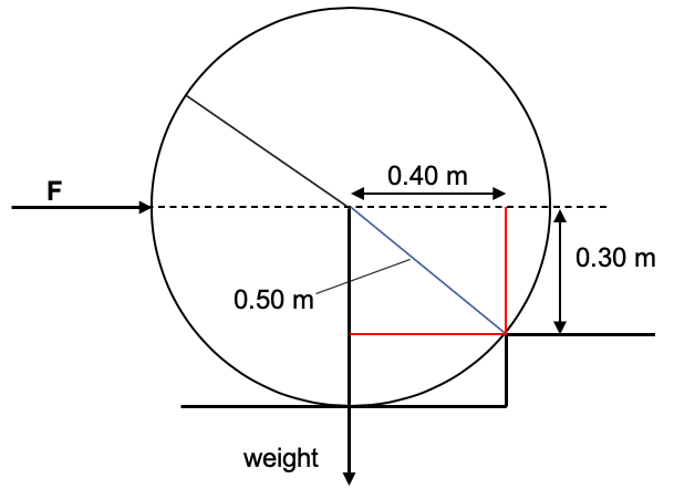
Noting that there is a right angled triangle and we have a 3-4-5 triangle, we are able to Identify the perpendicular distances from the lines of action of the forces to the pivot: Thus; Taking moments about the pivot, Clockwise moment = force x distance = F × 0.30 m = 0.3F N m Anticlockwise moment = force x distance = weight × 0.40 m = 20 × 0.40 = 8.0 N m Applying the principle of moments; 0.3F = 8 F = 27 N |
| Example 5 |
|---|
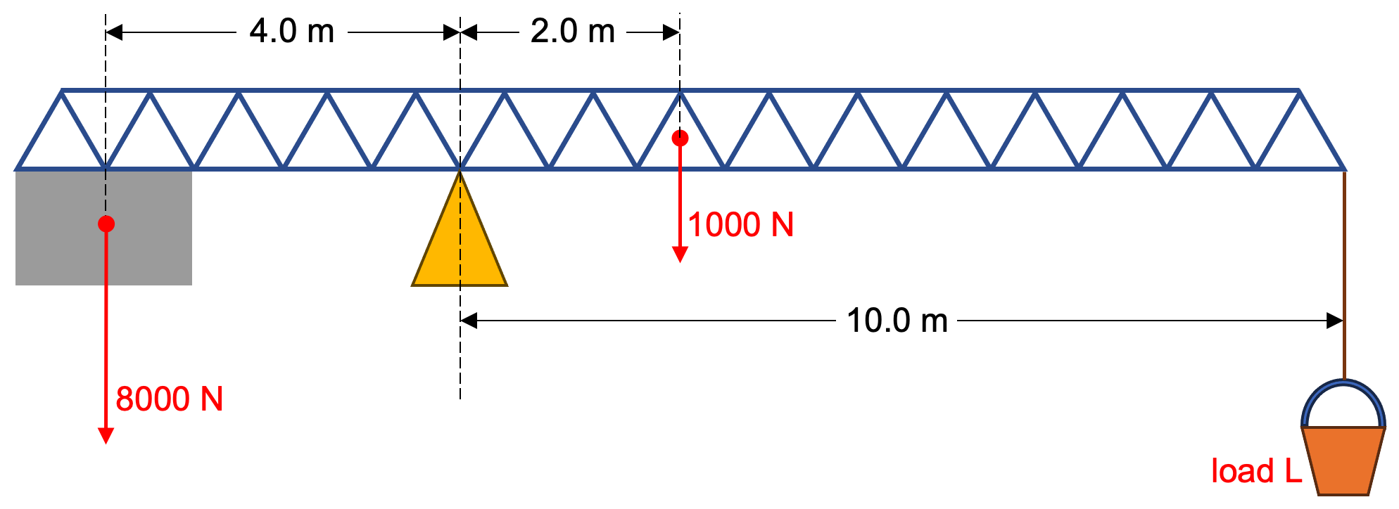
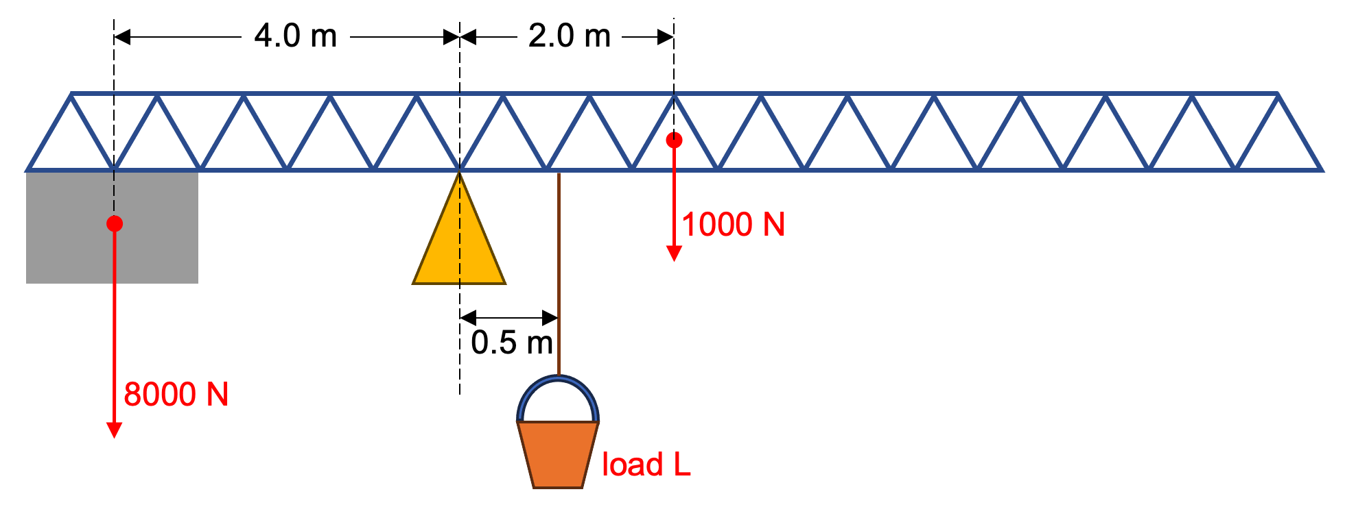
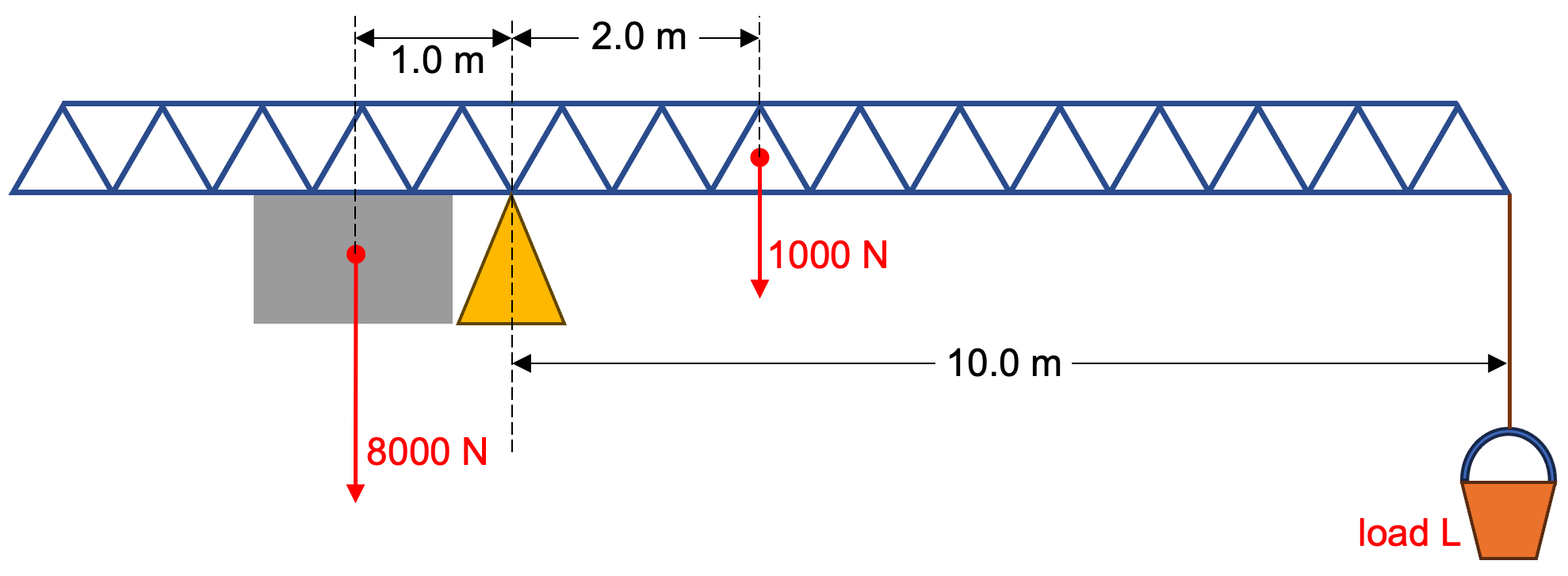
| The jib of a crane (in blue) has a weight of 1000 N. A load is balanced against a concrete weight of 8000 N. The concrete weight and the load L can be moved so as to maintain a balance.
The maximum distances for the concrete weight and load from the pivot are shown in the above diagram. The minimum distance of the concrete weight from the pivot is 1.0 m. The minimum distance of the load from the pivot is 0.5 m. (a) Determine the maximum load, LMAX the crane can carry. The maximum load will be carried when the concrete weight is as far from the pivot as possible and the load is as close to the pivot as possible. anticlockwise moments = clockwise moments 8000 × 4.0 = LMAX × 0.5 + 1000 × 2.0 LMAX = 60 000 N
(b) Determine the minimum load, LMIN the crane can carry. The minimum load will be carried when the concrete weight is as close to the pivot as possible and the load is as far from the pivot as possible. anticlockwise moments = clockwise moments 8000 × 1.0 = LMIN × 10.0 + 1000 × 2.0 LMIN = 600 N |
| << Back | Turning Effects of a Force | Next >> |