The Simple D.C. Electric Motor
The motor consists of a few components, such as the coil and commutator. We will first look at these separately before seeing how they combine in a simple d.c. motor.
Force on a Current-Carrying Coil (in a Magnetic Field)
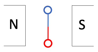
Consider a rectangular coil ABCD carrying a current placed in a uniform magnetic field.
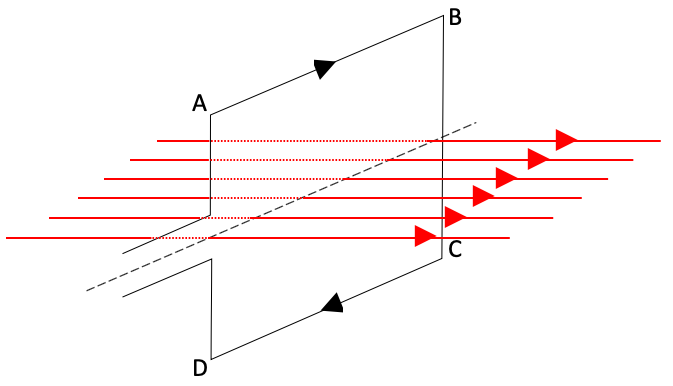
The magnetic field here is shown going left-to-right, and the current going around the coil from A-B-C-D.
The coil is currently in the vertical position and is perpendicular to the magnetic field, however, it is free to rotate about its axis (dotted line).
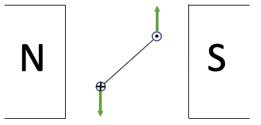
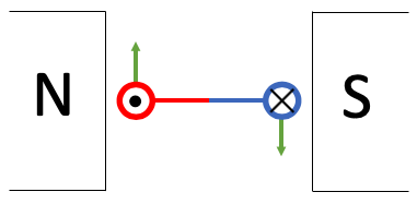
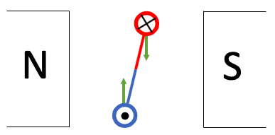
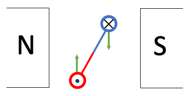
If we view this from the side of the coil we will see something like this:
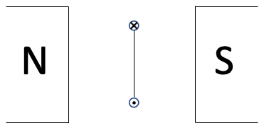
By applying Fleming’s Left Hand Rule we can see the forces acting on the sides AB and CD.
At this point of rotation of the coil, the force on AB is downwards and the force on CD is upwards. Hence the net force on the coil is zero newtons. The net moment is also zero newton-metres as the line of action of both forces passes through the pivot (centre line of the coil – the axis of rotation).
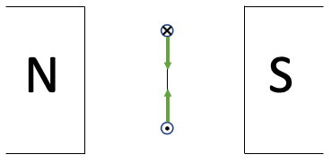
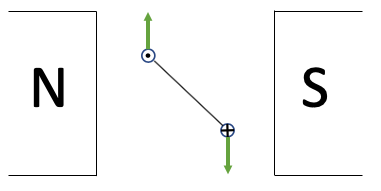
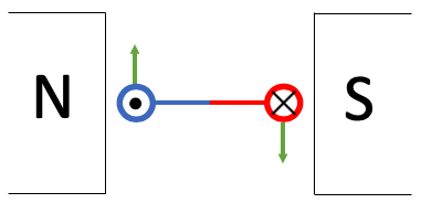
If we turn the coil through 90° and consider the forces acting on the coil then, we get the following:
At this point of rotation of the coil, the force on AB (the left side) is downwards and the force on CD (right side) is upwards. Hence the net force on the coil is still zero newtons.
However, as the line of action of both forces do not pass through the pivot there is a net moment. Both forces are contributing to an anticlockwise turning moment.
In fact at this position (coil parallel to the magnetic field) the net moment is at a maximum.
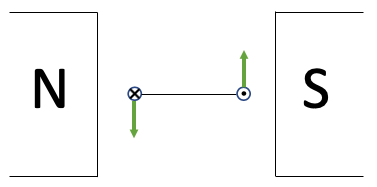
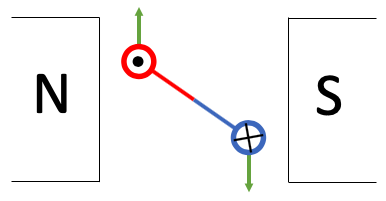
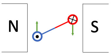
When the coil is at some other angle, like this:
The net force is still zero.
There is a net resultant anticlockwise moment, however, it is less than in the above situation as the lines of action of the forces have moved closer to the pivot.
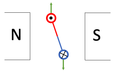
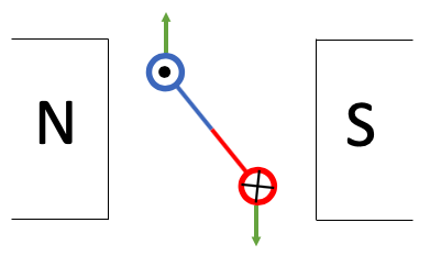
Note: If if the coil is rotated to a position like shown below, then the moment will be anticlockwise.
Thus we would not be able to get a coil to spin continuously in the same direction if the current in the coil continued to flow the same way around the coil.
Split-Ring Commutator
The coil is connected to the external wiring (eg a battery) via a split-ring commutator. The split-rings are connected to the ends of the wire that form the coil. They spin around with the coil.
The function of the split-ring commutator is to reverse the direction of current in the coil every half cycle. Hence, the direction of the force will be reversed on each side of the coil every half cycle such that the net moment will be in the same direction. This will allow the coil to continue rotating in the same direction.
Function of Carbon Brush
The function of the brush is to maintain good electrical contact between the external (non moving) circuit and the rotating split ring commutator. Ideally, whilst providing as little friction as possible. A common material for the brush is graphite (a form of carbon) due to its good electrical conductivity and lubricating properties.
Originally, brushes were made of many tiny wires bunched together (an actual brush). This would wear out fairly quickly and so the change to graphite (which also wears, but much more slowly) allowed motors to last longer.
The D.C Motor
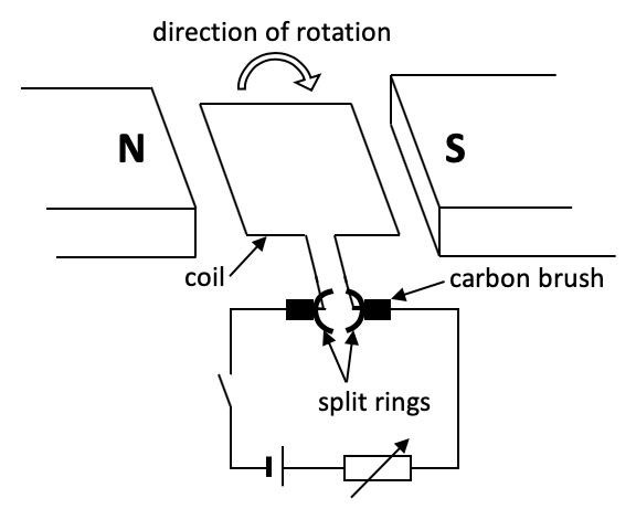
The above diagram shows the main components of a simple d.c motor.
Watch the following videos to get a good visualisation as to how the split ring commutator works.
| https://youtu.be/Jg4BkhyNbRg |
| https://youtu.be/LAtPHANEfQo |
In the above example:
- the torque is maximum when the coil is horizontal,
- the torque is zero when the coil is vertical,
- the current will change direction in the coil as the coil passes the vertical position
To help us visualise this lets imagine each half of the coil is different colour. This will help us to track it as it rotates.
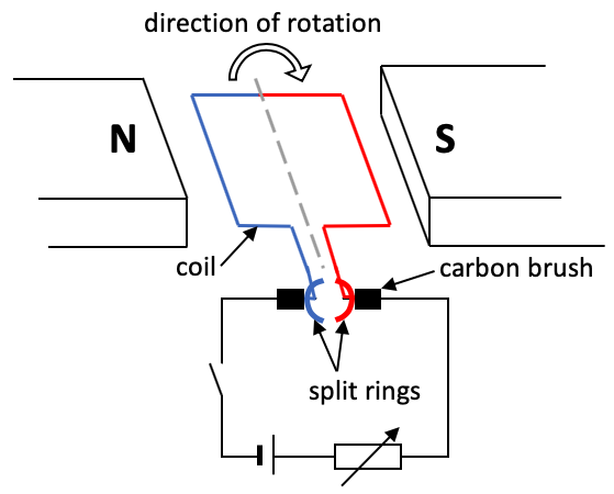
 1. Initially in the horizontal position. A current is flowing around the coil – into the blue side and out of the red side. The coil has a large torque (moment) on it due to the two forces acting along each wire.
 2. The moment will cause the coil to rotate clockwise.
 3. As the coil rotates the forces are still in the same direction on each side of the coil. But as the distance between the forces and the pivot decreases, the moment gets smaller.
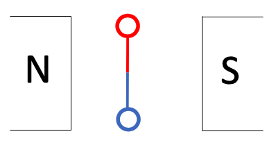 4. In the vertical position the split rings are swapping contact from one brush the the other. For a short while there is no current flowing in the coil. However, as the coil was already moving, inertia will keep it rotating past the vertical position.
5. The brushes touch the slip-rings again and current once again flows though the coil. However, the current is now flowing the opposite way around the coil. It’s now into the red side and out of the blue side.
 6. The current having changed direction results in the forces on the red and blue sides changing direction, which keeps the coil rotating in the same direction.
 7. The coil continues to spin clockwise. It will reach maximum torque when in the horizontal position again.
 8. And decrease torque as it heads towards the vertical position.
 9. When vertical, once again, the current stops for a while as the slip-rings cross over from one brush to another. Again the inertia due to its movement will keep the coil spinning past the vertical position.
 10. continues spinning
11. Finally we arrive with the coil back at the staring position and the whole process will start again.
How can the motor be made to turn faster?
- Increase the strength of the permanent magnets.
- Increase the current through the
In what ways would a real motor be different from this simple d.c. motor?
| Example |
|---|
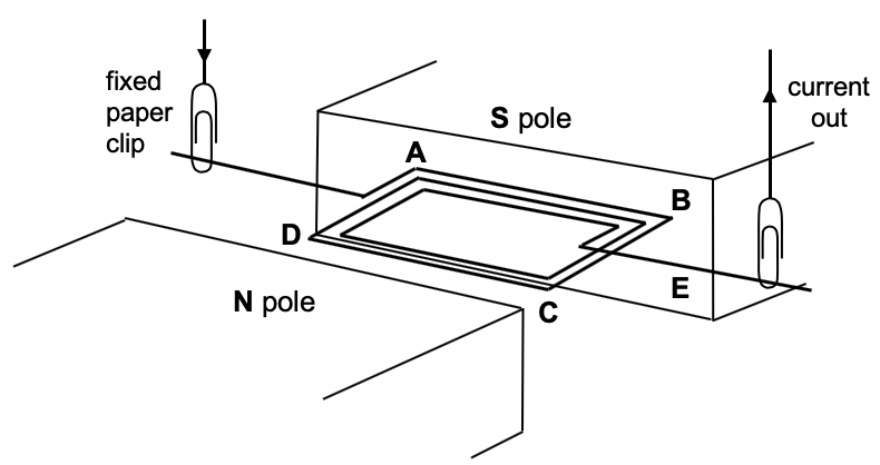
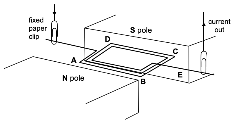
| The diagram below shows a coil ABCD that can turn between the poles of a magnet. Bare metal paper clips support and pass current into and out of the coil.
(a) State the direction of current on the side AB and on the side CD side. Hence state the direction of the force on sides AB and CD.
Knowing the directions of the magnetic field and current in each side of the coil, we use Fleming’s Left Hand Rule to determine the direction of the forces.
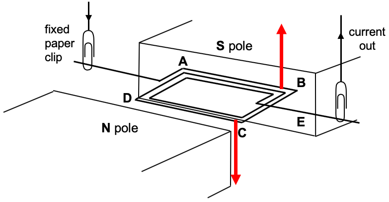
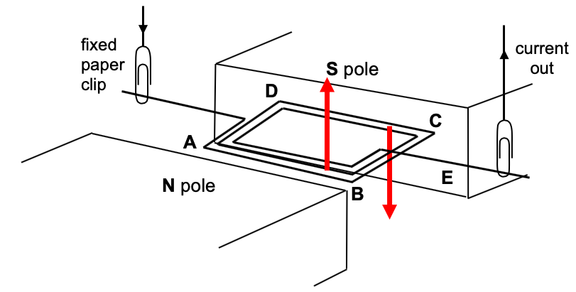
(b) A student turns the coil through 180° so that AB is close to the N pole of the magnet as shown below.
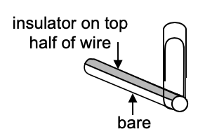
The current will still flow in the direction A to B along the wire AB and still C to D along the wire CD. The side AB will continue to experience an upward force, the side CD will continue to experience a downward force. The coil will not rotate continuously. When the coil makes a 180° turn, as the force on AB remains upwards. Hence an opposite moment is produced which prevents the coil from rotating continuously. (c) Explain the difference that would result if the top half of wire E is coated with an insulator, as shown in the enlarged view below.
When the coil rotates until the insulated part of the wire is below and makes contact with the paper clip, the current will be cut off.However, the momentum (or inertia) of wire AB causes it to continue to rotate in the same direction. Half a cycle later, the non-insulated part of the wire makes contact with the paper clip again. Current flows through the coil and forces and a net moment are produced to keep the coil rotating in the same direction. Note: The bare half of the wire does not act as a commutator, as current is not reversed every half a cycle. |
| << Back | Electromagnetism |
| Links |
|---|
| https://www.edumedia-sciences.com/en/media/50-dc-motor |
| https://www.walter-fendt.de/html5/phen/electricmotor_en.htm |