A transformer is a device that changes a high alternating voltage (at low current) to a low alternating voltage (at high current) and vice versa.
It is used for:
-
- electrical power transmission from power stations to households and factories, and
- regulating voltages for proper operation of electrical appliances, e.g. the television and CD player
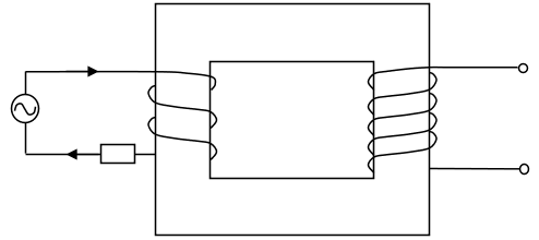
Circuit symbol:
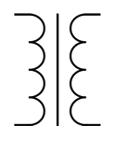
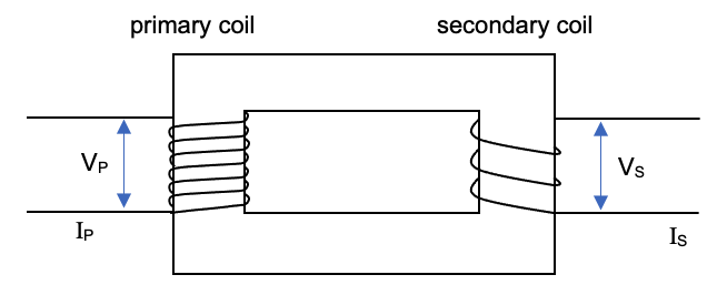
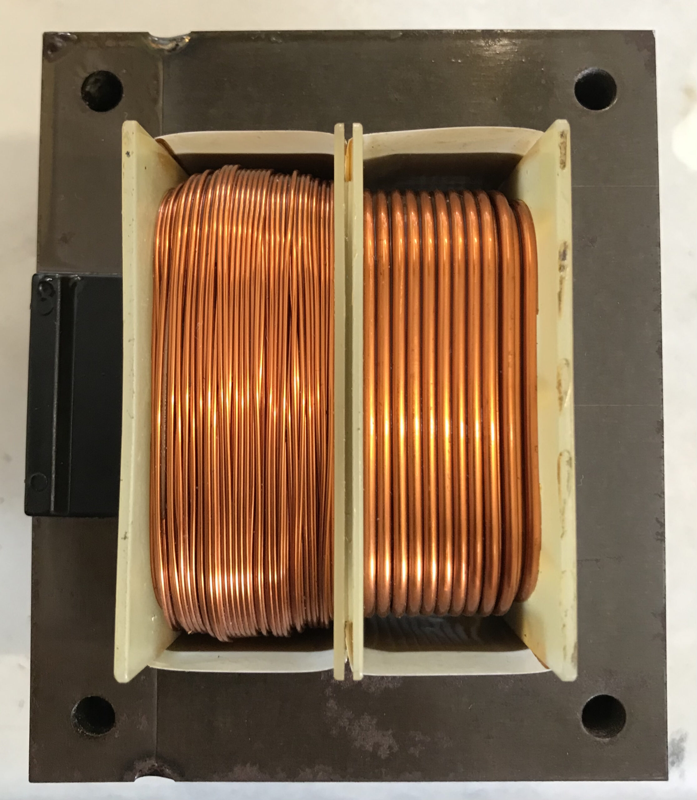
A transformer typically consists of two coils wrapped around an iron core.
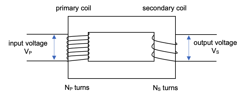
The current /voltage is input on one side (known as the primary coil) and the output received at the other (secondary coil).
VP represents the voltage applied to the primary coil (the input voltage).
VS represents the voltage existing across the secondary coil (the output voltage).
NP represents the number of turns /windings in the primary coil.
NS represents the number of turns /windings in the secondary coil.
| turns vs coils |
|---|
| Do not say the primary side ‘has more coils than the secondary’
They actually both have one coil! You should say: ‘there are more windings on the primary coil than the secondary coil’ |
Turns ratio is the number of turns in the secondary coil / number of turns in the primary coil.
Turns Ratio= NS / NP
The turns ratio is equal to the ratio of the output / input voltages across the coils.
NS / NP = VS / VP
If there are more turns in the primary coil (i.e. turns ratio is less than 1) then the output voltage will be lower than the input voltage. This is called a step-down transformer. The voltage is lowered (stepped-down).
If there are less turns in the primary coil (i.e. turns ratio is more than 1) then the output voltage will be higher than the input voltage. This is called a step-up transformer. The voltage is increased (stepped-up).
What type of transformers are most common in your house?
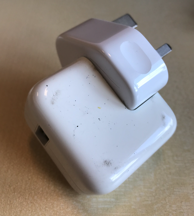
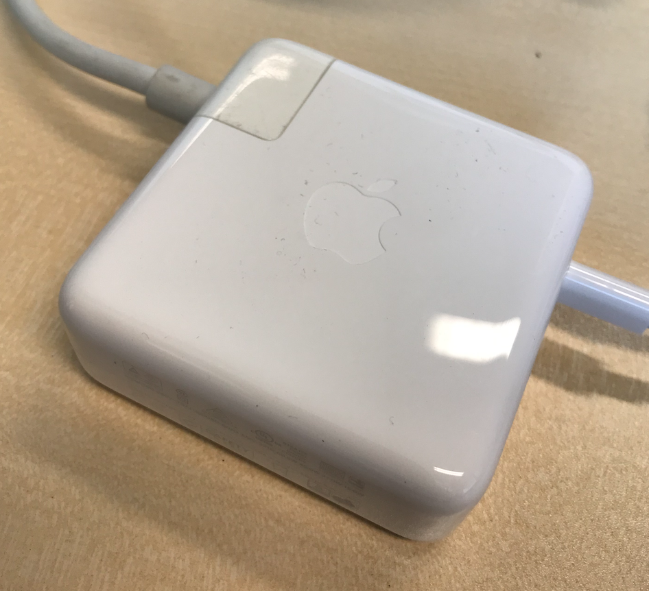
Typical transformers you may find around the home look like this. They are placed between the a.c. supply (240 V in Singapore) and the appliance.
Q: Do you think these are step-up or step-down transformers?
Many larger electronic appliances may not have an external transformer like those shown above. However, that usually means that the transformer is incorporated into the appliance itself.
It might seem strange that we can increase the voltage using a transformer, and you may be wondering if this is defying the Principle of Conservation of Energy? It does not!
To understand this we need to think about the current that is flowing in different parts of teh circuit…
Power & Current in a Transformer
There will, obviously, be currents flowing through each coil (we are assuming both coils are parts of closed circuits).
The current flowing in the primary coil, IP, is not the same as the current flowing through the secondary coil, IS. They are two separate circuits. They are joined by magnetic fields, there is not an electrical connection between them.
In fact an ideal transformer (one that has no power losses) the magnetic field will transfer 100% of the electrical power across from the primary circuit to the secondary circuit.
i.e. the power input into the primary coil must equal the power output at the secondary coil.
Pin = Pout
Recall electrical power is given by:
P = I V
therefore,
IP × VP = IS × VS
VS / VP = IP / IS
Combining this with the earlier equation we get:
NS / NP = VS / VP = IP / IS
| Example 19.5 |
|---|
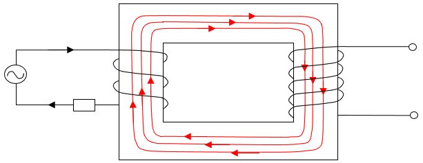
| Below shows a simple transformer.
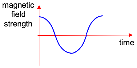
The coil on the left is connected to an a.c. power source. At the instant shown, the current is at its maximum positive value. (a) Indicate the direction of the magnetic field in the core at the instant shown
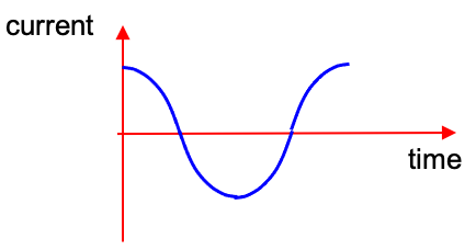
(b)(i) Sketch current against time for the left-hand coil.
(b)(ii) Sketch magnetic field strength against time for the left-hand coil.
(c) Describe the effect of the current in the left-hand coil on the right-hand coil. |
| Example 19.6 |
|---|
|
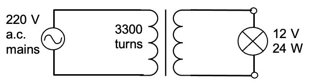
A transformer has 3300 turns in its primary coil and is used to operate a 12 V 24 W lamp from the 220 V a.c. mains.
(a) Draw a labelled circuit diagram showing the above connection.
(b) Assuming there is no power loss in the transformer, find (i) the number of turns in the secondary coil,
(ii) the current in the secondary coil,
(iii) the current in the primary coil, |
| Example 19.7 |
|---|
| In the following circuit, a lamp is connected to the secondary coil of the transformer by long leads (or cables) which have a total resistance of 2.5 Ω. The resistance of the leads is represented by a single resistor of 2.5 Ω.
The input power of the transformer is 40 W, and the transformer is 100% efficient. (a) the turns ratio of the transformer.
(b) the voltage across the secondary coil of the transformer.
(c) the current in the secondary coil of the transformer.
(d) the voltage across the long leads.
(e) the electrical power dissipated in the long leads.
(f) the electrical power dissipated in the lamp. |

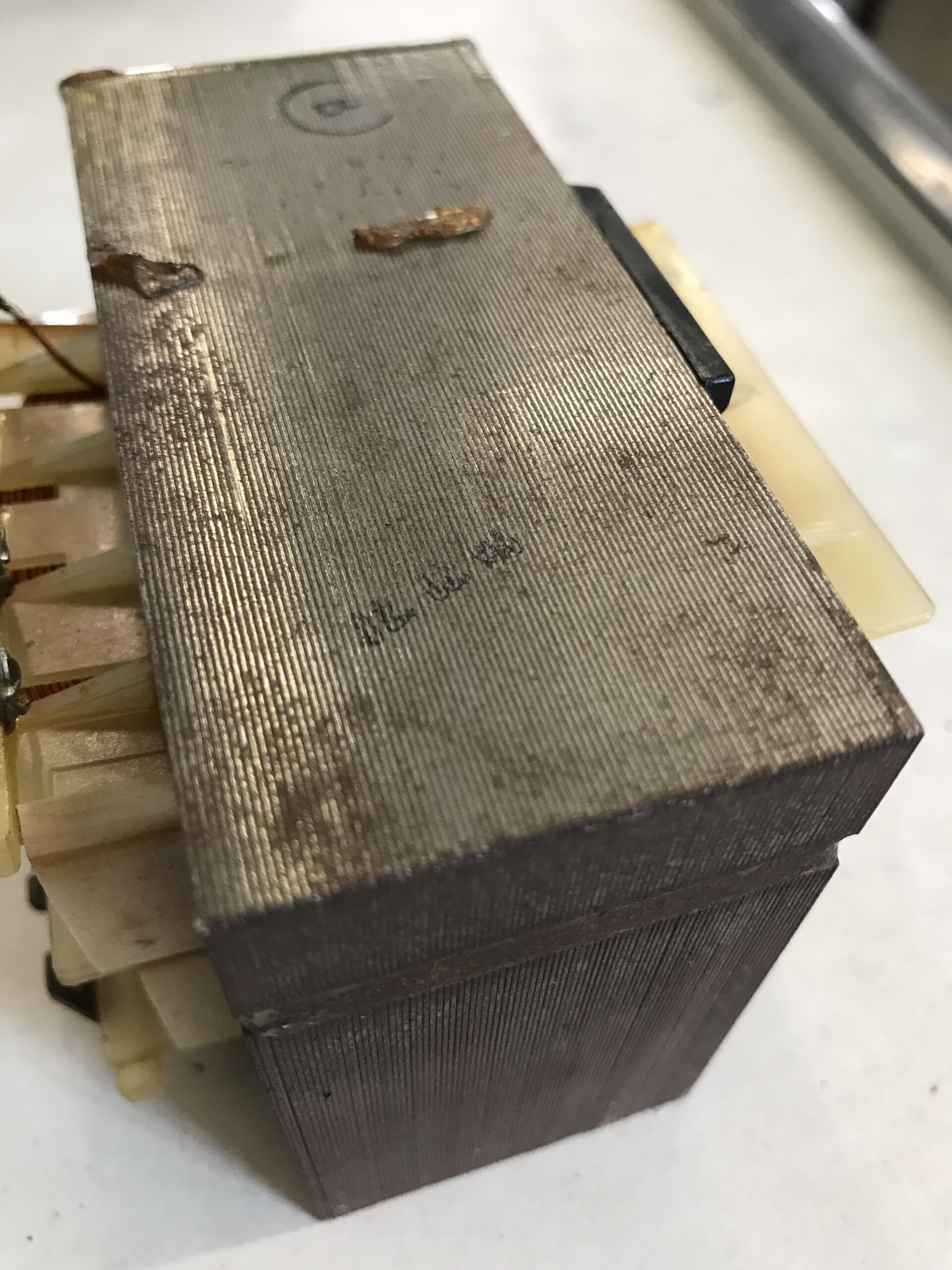
Here we can see the side view of the iron core. Notice that it is not a solid lump of iron, but is actually made of many thin sheets of iron sandwiched together. This is called lamination and helps to minimise formation of electric currents within the core. Any eddy currents formed within the core would reduce the efficiency of the transformer.
| << Back | Electromagnetic Induction | Next >> |