A thermistor is a thermal resistor whose resistance changes (either increases or decreases) with temperature.
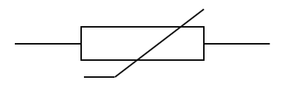 Thermistor Symbol
The I-V Characteristic graph for a thermistor looks like this:
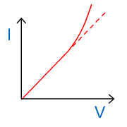
I-V graph for a thermistor
At higher voltages, the resistance of the thermistor decreases.
This can be explained by the larger currents raising the temperature and thus creating more free electrons in the thermistor.
Negative Temperature Coefficient (NTC) thermistors are more commonly used than Positive Temperature Coefficient (PTC) thermistors. NTC thermistors have a resistance that decreases as temperature increases, while PTC thermistors have a resistance that increases as temperature increases.
| Note |
|---|
| Some thermistors show an increase in resistance with temperature (ie PTC thermistors). The I-V graph for these will obviously curve in the opposite direction to the one shown above.
You will need to read the question carefully to be sure which type of thermistor you are dealing with. |
| Example 1 |
|---|
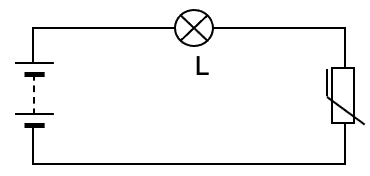
| The circuit shows a lamp L and a thermistor connected in series. This thermistor has a negative thermal coefficient.
Does the lamp L get brighter or dimmer if the thermistor is heated? Explain.
|
| Example 2 |
|---|
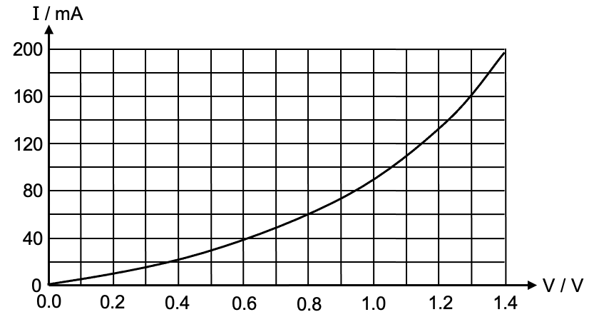
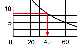
| A thermistor is connected to a d.c. supply. The voltage V across and the current I through the thermistor are measured as the voltage V is increased. At each stage, the temperature of the thermistor is allowed to reach a steady value before the meter readings are recorded. The graph below shows the resulting variation of current I with voltage V.
(a) Determine the resistance of the thermistor when the p.d. across it is 1.3 V.
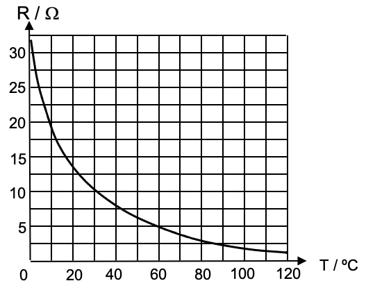
The resistance of the thermistor is given by the following chart:
|
| Example 1 |
|---|
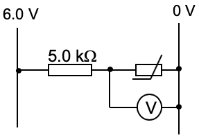
| In the circuit shown, a thermistor is connected in series with a 5.0 kΩ fixed resistor.
When the temperature is high, the resistance of the thermistor is 1.0 kΩ and when the temperature is low, the resistance of the thermistor increases to 8.0 kΩ. (a) Determine the potential difference across the thermistor measured by the voltmeter, when the temperature is high.
(b) Determine the potential difference across the thermistor measured by the voltmeter, when the temperature is low. |


| Example2 |
|---|
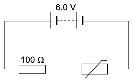
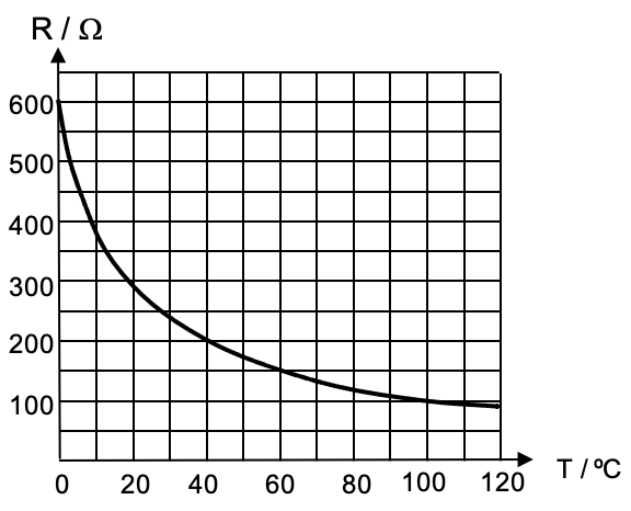
| The circuit below shows a thermistor connected in series with a 100 Ω resistor to a 6.0 V battery with negligible internal resistance.
The graph shows the variation of resistance R with temperature T of the thermistor.
Determine the difference between the minimum and maximum voltages across the thermistor as its temperature T increases from ice point (0 ºC) to steam point (100 ºC). |


| << Back | D.C. Circuits | Next >> |