A series circuit is a circuit in which all electrical components are connected one after the other to form a single loop.
In a series circuit there is only one path along which the electric current can flow.
Current in a Series Circuit
| Current at all points in a series circuit is the same. |
It doesn’t matter where an ammeter is placed in a series circuit.
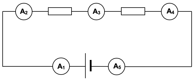 In this series circuit:
A1 = A2 = A3 = A4 = A5
Potential Difference in a Series Circuit
| The sum of the p.d.s in a series circuit is equal to the p.d. across the whole circuit. |
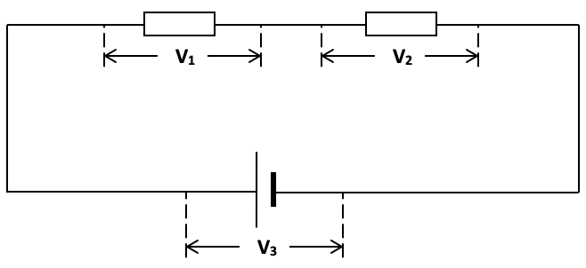
In this series circuit:
V1 +V2 = V3
Sometimes voltmeters will be shown connected across the components like this: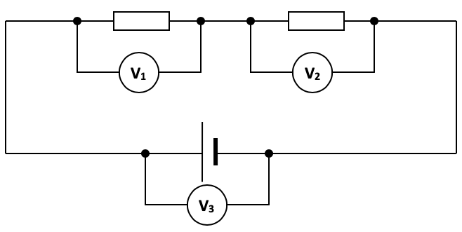
The p.d. across the whole circuit is also the e.m.f. across the source.
V3 = e.m.f. of the cell
Resistors in Series
The effective resistance of resistors in series is the sum of the individual resistances.
In equation form:
Re = R1 + R2 + R3
| Example 1 |
|---|
Consider the following three series circuits:   All three series circuits have an effective resistance of 10 Ω. Thus they could each be replaced by the following circuit. All three series circuits have an effective resistance of 10 Ω. Thus they could each be replaced by the following circuit. |
| Example 2 |
|---|
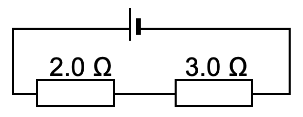
| Determine the effective resistance Re in the following circuit. Show all necessary working.
|
| Example 3A |
|---|
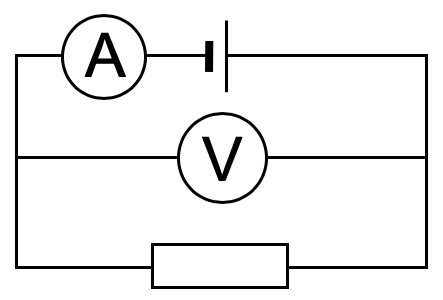
| A cell, an ammeter, a voltmeter and a resistor are connected as shown below.
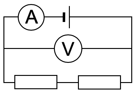
Given that the ammeter and voltmeter readings are 1.0 A and 2.0 V respectively, what are the new readings when an identical resistor is attached in series as shown below?
|
| Example 3B |
|---|
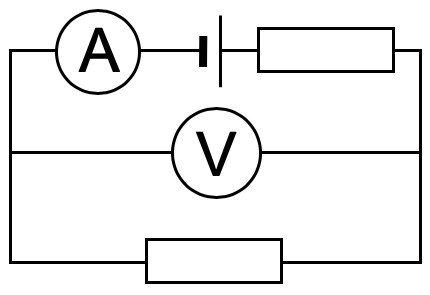
| A cell, an ammeter, a voltmeter and a resistor are connected as shown below.
Given that the ammeter and voltmeter readings are 1.0 A and 2.0 V respectively, what are the new readings when an identical resistor is attached in series as shown below?
|
| << Back | D.C. Circuits | Next >> |