The e.m.f. in a series circuit is divided among components according to the ratio of their resistances.
Consider the following circuit
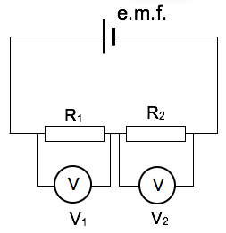 As the current flowing through the resistors is identical we can deduce the following relationship:
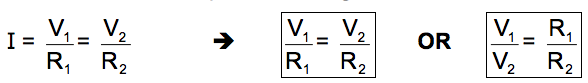
Alternatively, we can also compare the relationship between V and R for any resistor with the effective V and R of the whole circuit:
Effective resistance, Re= R1+ R2
| Example 1 |
|---|
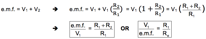
| The following circuit is set up.
(a) Using the potential divider concept describe and explain the changes in the reading of the voltmeter as the resistance of the rheostat is varied.
(b) Discuss whether the current drawn from the battery will change as the resistance of the rheostat is varied. |
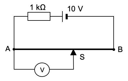
| Example 2 |
|---|
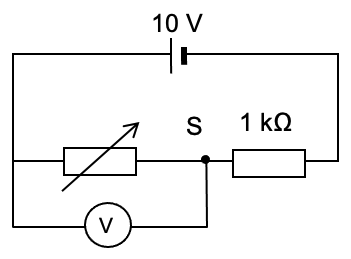
| In the circuit shown, AB is a length of resistance wire.
(a) Use the potential divider concept to describe and explain the changes in the voltmeter reading as the jockey S is slid along the length of resistance wire from A towards B.
(b) If the voltmeter is replaced by a high resistance light bulb, describe and explain the changes in the brightness of the lamp as the jockey S is slid along the length of resistance wire from A towards B.
(c) Describe and explain any change in the current drawn from the battery. |
If a rheostat used to vary the voltage of a circuit it is called a variable potential divider.
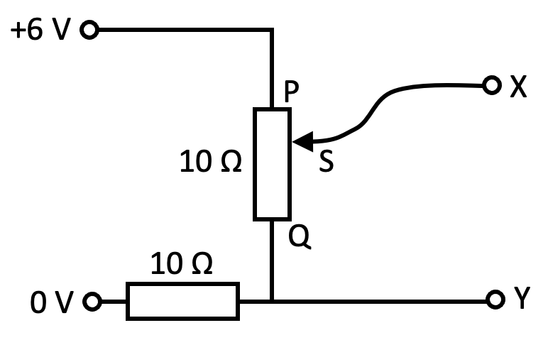
| Example 3 |
|---|
| A variable potential divider has a sliding contact S that can be moved between end P and end Q of a 10 Ω resistor. The potential divider is connected to a constant 6.0 V power supply and another 10 Ω resistor, as shown below.
What happens to the potential difference between X and Y as S moves from P to Q? |
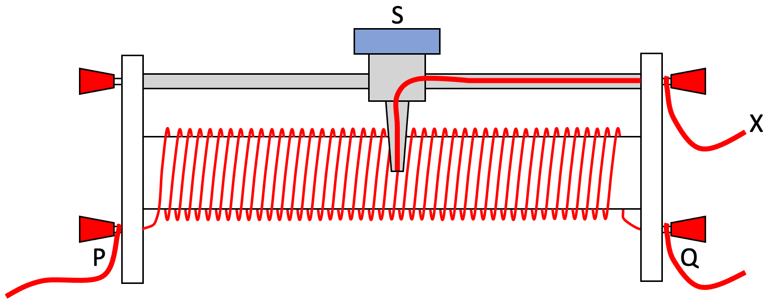
In the above example the rheostat could have been set up as follows:
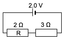
| Example 4 |
|---|
| What is the p.d. across resistor R?
|


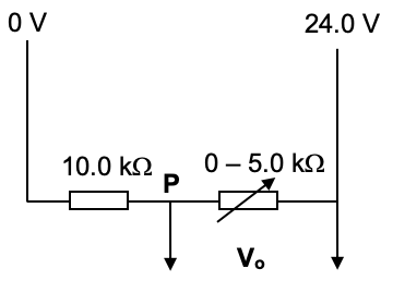
| Example 5 |
|---|
| The following circuit is set up:
(a) Use the potential divider concept to calculate the range of the output voltage, Vo
(b) determine the potential at point P of the circuit when the variable resistor is set at 2.0 kΩ. |


| Example 6 |
|---|
|
A student takes measurements of current and voltage to plot the I/V characteristic graph of a diode. The student connects the diode to the circuit containing a 1.5 V cell and a variable resistor Z, as shown in the diagram below.
By adjusting the slider, the potential difference across the diode is altered. (a) State the name of the device obtained by using the variable resistor in this way.
(b) On the diagram above, add an ammeter and a voltmeter in the correct positions that allow measurements for the I/V characteristic graph to be taken. |


| << Back | D.C. Circuits | Next >> |