In a parallel circuit, components are connected across two common points.
Charges going around the circuit will have two (or more) paths that they could take in making a complete journey around the circuit.
Current in a Parallel Circuit
| Current from the source is the sum of the currents in the separate branches of a parallel circuit. |
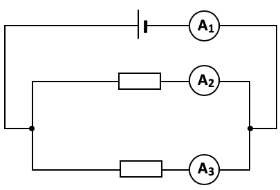

The current flowing out of the cell is the same as the current flowing back into it.
Also at any junction (node) the sum of the current flowing into the node must equal the sum of the current flowing out of the node.
The current need not split equally (in fact it will do so only if the resistance in each branch is identical).
Potential Difference in a Parallel Circuit
| The potential differences across each branch of a parallel circuit are the same. |
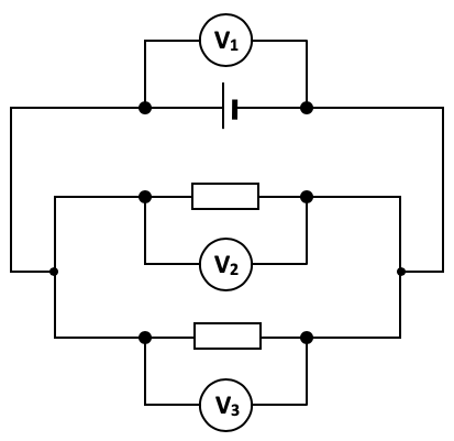 In this example
V1 = V2 = V3
Resistors in Parallel
| The reciprocal of the effective resistance for resistors in parallel is equal to the sum of the reciprocals of the individual resistances. |

| Example 1A |
|---|
|


| Example 1B |
|---|
|
|


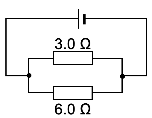
| Example 2A |
|---|
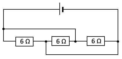
| Determine the effective resistance Re in the following circuit. Show all necessary working.
|


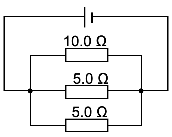
| Example 2B |
|---|
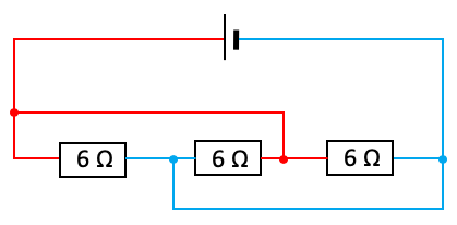
| Determine the effective resistance Re in the following circuit. Show all necessary working.
|


| Example 3 |
|---|
What happens to the brightness of the bulb as the resistance of the rheostat is slowly increased?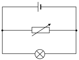
|
| Example 4 |
|---|
What happens to the ammeter and voltmeter readings when switch S is closed?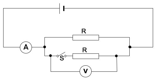
|
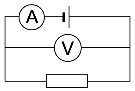
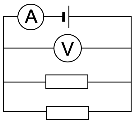
| Example 5 |
|---|
| A cell, an ammeter, a voltmeter and a resistor are connected as shown below.
Given that the ammeter and voltmeter readings are 1.0 A and 2.0 V respectively, what are the new readings when an identical resistor is attached in parallel as shown below?
|
| Example 6 |
|---|
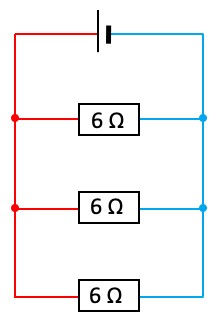
| What is the effective resistance of the following circuit?
|


| << Back | D.C. Circuits | Next >> |