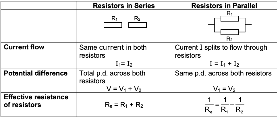
15.2.3 – Circuits with Series & Parallel Components
We have learnt how current and p.d. behave for series and circuits.
For circuits that have combinations of series and parallel sections we simply apply these rules to the different sections of the circuit.
Some useful points to remember:
The current entering a junction must equal the current leaving a junction.
The sum of the p.d.s around the circuit from one terminal of the battery to the other will be the same, irregardless of which route is taken. This will also equal the e.m.f. of the battery.
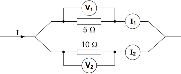
Example 1
Consider the following section of a circuit:
Let the current be 6.0 A.
The p.d. across each branch will be the same.
The current will split as the wires split. However, as the resistance in each branch is different, the currents will also be different.
As the resistance in the bottom branch is twice that of the top branch, the current flowing in the bottom branch, 2, will be half of that of 1.
Thus 1 =4.0 A and 2 = 2.0 A.
The resistances can be calculated from:
V1 = 1 × R1 = 4.0 × 5 = 20 V
V2 = 2 × R2 = 2.0 × 10 = 20 V
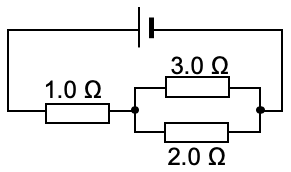
Question 1: Effective Resistance
Calculate the effective resistance of the following circuit .
The 3.0 Ω resistor and 2.0 Ω resistor are in parallel with each other and so the effective resistance of this pair should be determined first:
Now we have simplified the circuit to 1.0 Ω in series with 1.2 Ω.
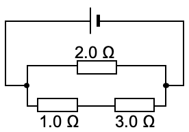
Calculate the effective resistance of the following circuit.
In this circuit the 1.0 Ω and 3.0 Ω resistors are in series, so we need to find the effective resistance of these two first.
Effective resistance = 1.0 Ω + 3.0 Ω = 4.0 Ω
Now we have simplified the circuit to a 2.0 Ω resistor and a 4.0 Ω resistor in parallel. The effective resistance of this arrangement can thus be found:
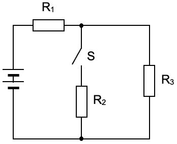
Question 3
The diagram shows a network of resistors R1, R2 and R3 connected to a battery.
When the switch S is closed, the potential difference (p.d.) across R2 rapidly increases to a steady value.
What happens to the p.d. across each of the other two resistors?
Let’s put some values into the question to help us see what is going on. Let the emf of the battery be 6 V and the resistance of each resistor be 10 Ω.
When the switch is open, no current flows through R2 and thus identical current will be flowing through R1 and R3. The p.d. across each is hence identical and will be 6 V ÷ 2 = 3 V.
When the switch is closed, current splits and 50% passes through R2 and 50% through R3. Thus as a smaller current flows through R3 (compared to R1) it will have a smaller p.d. across it.
Alternatively we can think of R2 and R3 in parallel (each of 10 Ω) having an effective resistance of 5 Ω. Thus the p.d. across R1 (10 Ω) will be twice that across the pair of other resistors (with effective resistance of 5 Ω). i.e. there will be 4 V across R1 and 2 V across R3.
Thus when the switch is closed, the p.d. acrossR1 will increase and the p.d. across R3 will decrease.
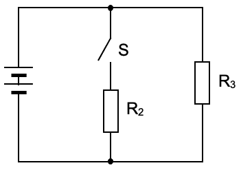
Note
The question would have been much simpler if the circuit was like this:
In this case the p.d. across R3 will not change as S is opened and closed as R3 is connected directly across the battery.
This circuit is purely parallel. The original circuit is a combination of parallel and series sections.
 be 6.0 A.