- Resistance is the ability of a substance to resist the flow of charge through it.
- A good conductor has low or negligible resistance, while a poor conductor has a high resistance.
- When an electric current passes through a light bulb or filament lamp, the electrical energy is converted into heat and light
| Definition: Electrical Resistance |
|---|
| Resistance is defined as the ratio of the potential difference across a component to the current flowing through the component. |
In equation form:
 |
Where:
R – resistance (Ω)
V – p.d. across the component (V)
I – current flowing through the component (A)
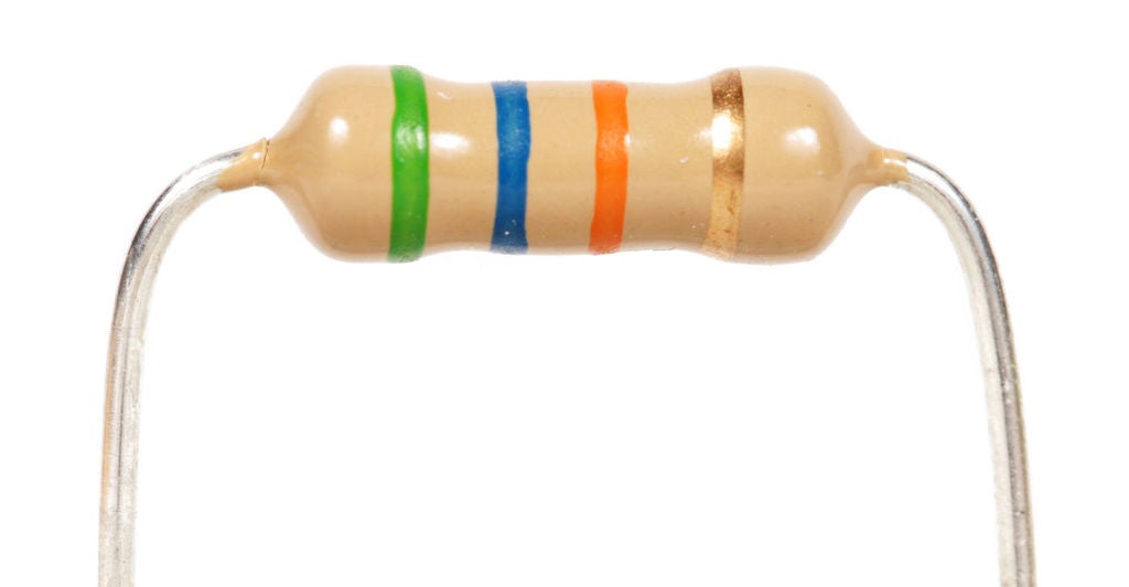
Resistors
Resistors are circuit components that convert electrical energy into heat.
| Resistor Colour Codes – You will not be tested on this | |||||||||||||||||||||||||||||||||||||||||||||||||||||||||
|---|---|---|---|---|---|---|---|---|---|---|---|---|---|---|---|---|---|---|---|---|---|---|---|---|---|---|---|---|---|---|---|---|---|---|---|---|---|---|---|---|---|---|---|---|---|---|---|---|---|---|---|---|---|---|---|---|---|
Most common resistors are so small that their values need to be indicated by colour rings rather than printing words on them.
An additional band is often present to show the tolerance of the resistor. Some common examples are: Red: ±1%
|
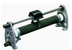
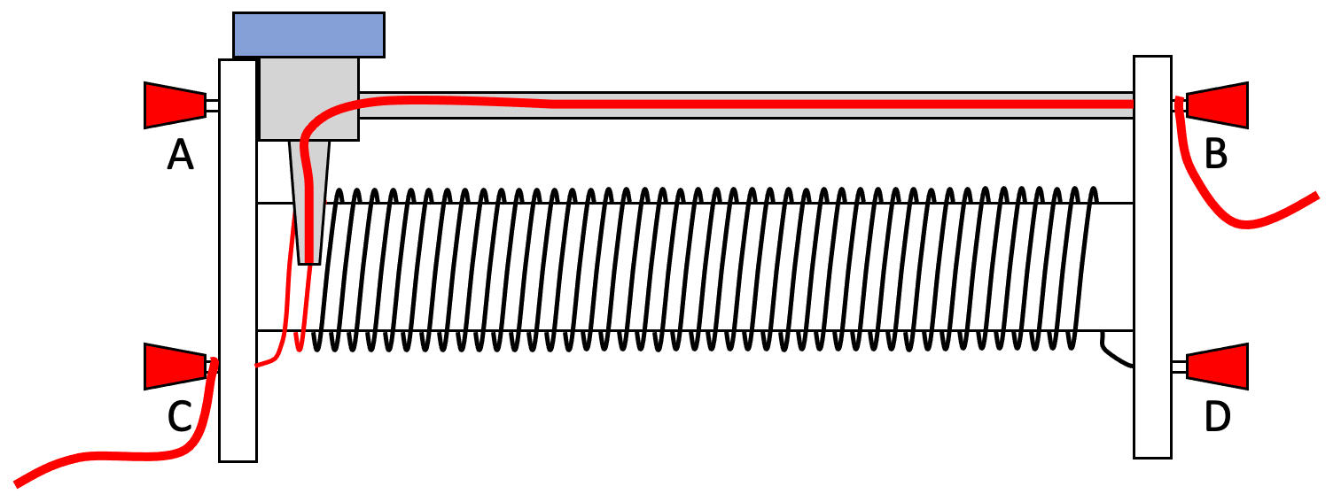
The Rheostat – A Variable Resistor
In the laboratory a rheostat is commonly used. The advantage of this is that its resistance can be varied.
 A variable resistor (or rheostat) is an electrical component used in a circuit to vary the current flowing in a circuit.
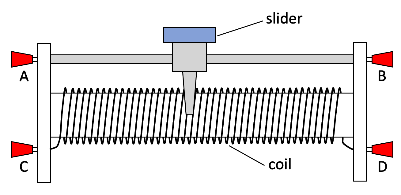
The resistance is provided by a coil of high resistance wire.
Most rheostats have four electrical terminals (A, B, C & D in the diagram below).
A and B are at either end of a metal (conducting) bar.
C and D are at either end of the coil of resistance wire.
A slider is able to slide along the metal bar whilst having an electrical connection to the coil, thus allowing current to flow between the bar and the coil.
Usually wires are connected on diagonally opposite connectors. (C and B are used in the diagram below.)
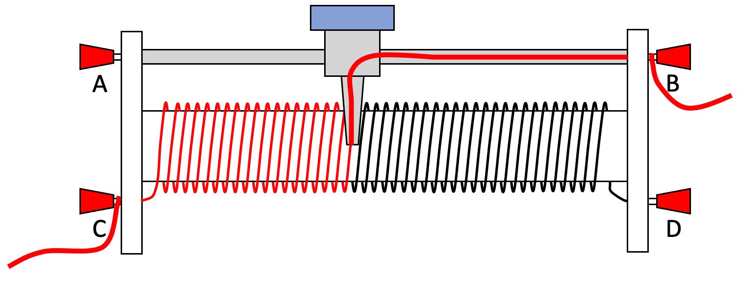
The red lines show the path of current flowing through the rheostat.
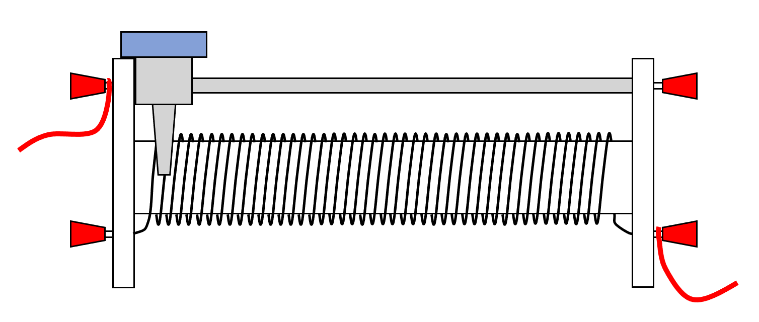
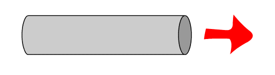
If the slider is slid all the way to the left then the current flows through very little of the coil and the resistance of the rheostat will be a minimum.
 Rheostat set to minimum resistance
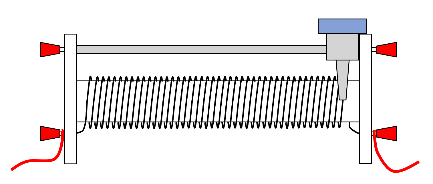
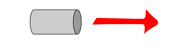
If the slider is slid all the way to the other end then the current is made to flow through all of the coil and the resistance will be a maximum.
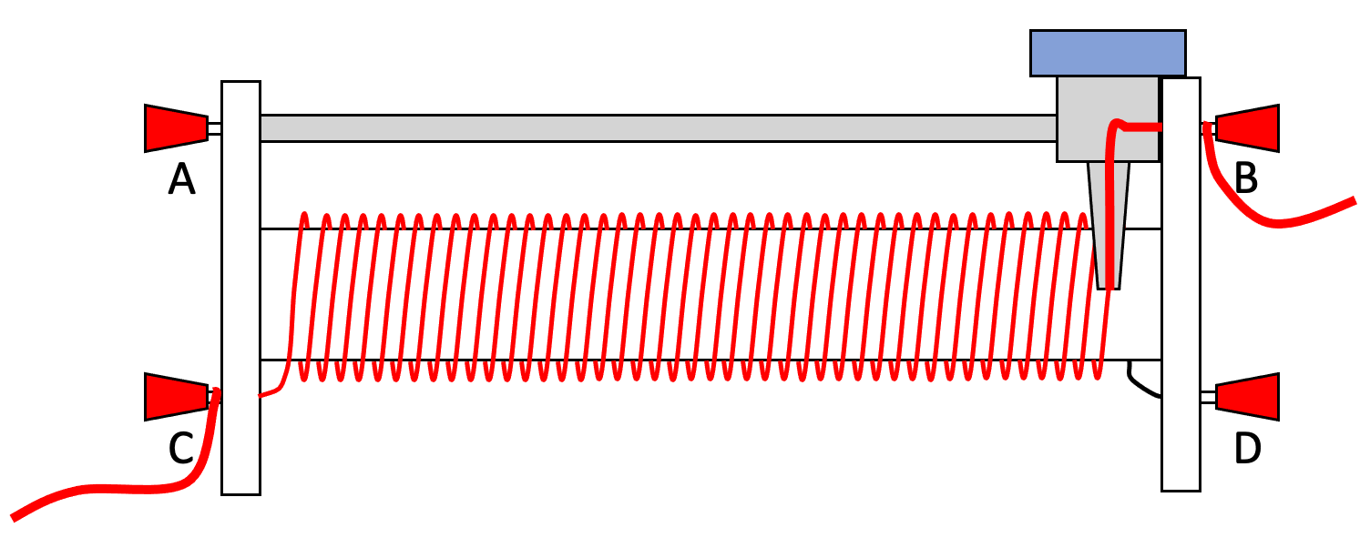
Rheostat set to maximum resistance
| Example 1: Rheostat |
|---|
| Is the following rheostat set at a maximum or a minimum resistance?
|
| Example 2: Rheostat |
|---|
| What will be the effect of moving the slider left, starting from the position shown below?
|
High Power Resistors
These are frequently used in the laboratory. They are large enough to have their resistance written on them, although at first it may be hard to decipher the value.
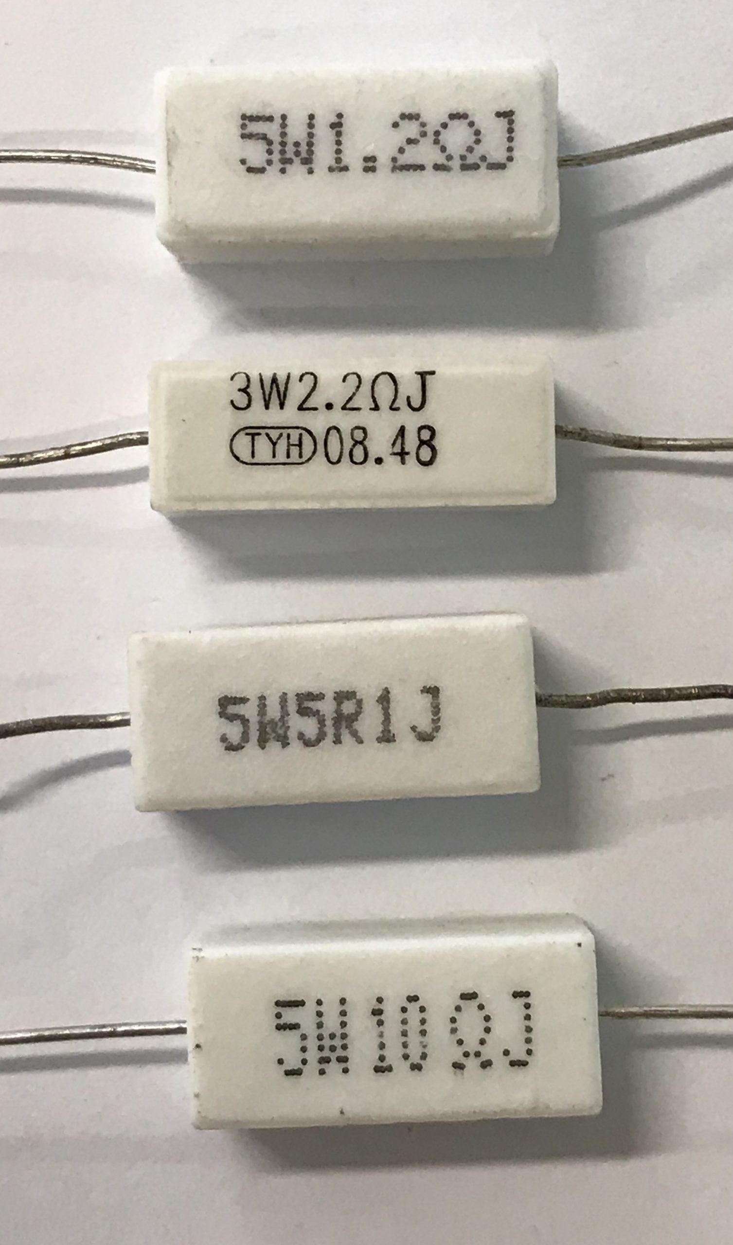 1.2 Ω, 2.2 Ω, 5.1 Ω and 10 Ω resistors in the lab
eg
5W1.2ΩJ is a 5 watt resistor that has a resistance of 1.2 Ω.
5W5R1J is a 5 watt resistor that has a resistance of 5.1 Ω.
Factors Affecting Resistance
The resistance of a wire will depend on a number of factors. Namely:
- length of the wire
- thickness of the wire
- material of the wire
A. Length of the Wire
The longer the wire the more the resistance of the wire and hence the smaller will be the current flowing in the wire.
 long wire = high resistance = small current
 short wire = low resistance = high current
Experimental results show that the resistance R of a conductor is directly proportional to its length (l)
B. Thickness of the Wire
In fact it is the cross-sectional area that we are interested in here. Just like drinking Coca-Cola through a straw, the straw offers some resistance to the flow of drink through the straw.
 thin wire = high resistance = small current
 thick wire = low resistance = large current
Experimental results show that the resistance R of a conductoris inversely proportional to its cross-sectional area (A)
For a wire of diameter d,
where A = π r2 = π (½d)2 = π d2/4
C. The Material that the Wire is Made From
Resistivity (ρ) is the property of the material that determins its resistance. The resistivity of several common materials is stated below.
| Material | Resistivity / Ω m |
|---|---|
|
Silver
|
1.6 x 10⁻⁸
|
|
Copper
|
1.7 x 10⁻⁸
|
|
Iron
|
9.8 x 10⁻⁸
|
|
Constantan
|
49 x 10-8
|
|
Nichrome
|
100 x 10-8
|
|
Polythene
|
~1016
|
The resistance of a conductor may change (due to change in resistivity ρ) as temperature changes. In particular, for a metallic conductor, and a filament lamp, their resistance increases as temperature increases.
combining these factors we get:
 |
Where:
R – resistance (Ω)
ρ – resistivity of the material (Ω m)
l – length of the conductor (m)
A – cross-sectional area of the conductor (m²)
| Cross-Sectional Area or Width? |
|---|
| The above formulae refers to the cross-sectional area of the wire. Questions will sometimes refer to the diameter of the wire.
If the diameter of the wire is halved, the resistance goes up by four times.
|


| Example 1A |
|---|
| Wire A is made of a material whose resistivity is twice that of wire B. In addition, the cross-sectional area of wire A is thrice that of wire B.
What is the ratio of the resistance of wire A to the resistance of wire B? |
| Example 1B |
|---|
| A 1.5 m long wire made of material X has a resistance of 6.0 Ω.
What is the resistivity of the material X if the cross-sectional area of the wire is 1.0 mm2? |
The resistance of connecting wires is assumed to be zero Ω.
The internal resistance of an ideal ammeter is zero Ω.
The internal resistance of an ideal voltmeter is infinitely high.
The internal resistance of a cell or battery is assumed to be negligible.
| Advanced Physics Topic: Internal Resistance of Battery |
|---|
| Most batteries do have a resistance. This is taken into account in advanced problems (eg A Level) when the value of the internal resistance of the battery will be given.
|

| << Back | Current of Electricity | Next >> |