(Optional Physics Topic – Not Tested)
To get a better understanding of the terms potential difference and electromotive force it is helpful to have an understanding of the concept of electric potential in a circuit.
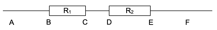
| To understand this concept better an analogy of a ball rolling down a sloped track as shown below may help:
As it rolls down BC it will lose gpe. Thus as it moves along CD has less gpe than it did along AB. So comparing the ball at different points along the track, at different points (heights) it will have it will have different amount of potential energy. At EF it has the lowest gpe. We could get the ball to roll down again, but first would need to lift it back up to the start point (ie give it more gpe).
In a circuit the wires (perfect conductors) are like the flat parts of the track- no potential difference exists along each. Resistors (or other circuit components) will result in a potential change (drop) as the current passes through them:
Wire AB can be considered to be at a high electrical potential (ie connected to the positive terminal of a battery). CD is all at the same potential, but a lower potential than AB. Likewise EF is the part of the circuit at the lowest potential. To make the charges move around in a loop a source of energy would be needed to move the charges up to a higher potential again. |

Imagine a simple circuit with a battery supplying electricity and a bulb and a resistor ‘using’ the electricity.
As charges pass through the cell a potential is created across the two terminals. Here we are imagining a 12V battery. By convention the negative terminal is stated to be 0 V and so the positive terminal will be at a +ve potential.
The wire connected to the positive terminal will all be at the same potential.
Other wires in the circuit will also each be at constant potential but a decreasing potentail depending how far around the circuit they are.
The last wire (connecting to the negative terminal of the battery) must of course be at zero potential.
If we connect a voltmeter across the lamp, one wire will be at 12 V potential and the other wire will be at 9 V potential. Thus the voltmeter will read a potential difference of 3 V.
If we connect a voltmeter across the resistor, one wire will be at 9 V potential and the other wire will be at 0 V potential. Thus the voltmeter will read a potential difference of 9 V.
If we connect a voltmeter across the battery, one wire will be at 0 V potential and the other wire will be at 12 V potential. Thus the voltmeter will show a potential difference of 12 V. However, as the battery is a source of e.m.f., we call this the e.m.f. of the battery, not p.d..
The sum of the p.d.s (3 V plus 9 V) is equal to the e.m.f. of the battery.
| Question 1 |
|---|
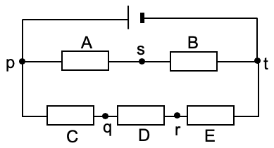
| Five resistors are connected to a cell as shown in the diagram. Resistors C, D and E are identical. The potential at point t is zero and the p.d. across resistors A and B are 0.8 V and 0.7 V respectively.
(a) What is the e.m.f. of the cell?
(b) What are the potentials at points s and q?
(c) State the p.d. between s and q? |
| Question 2 |
|---|
| What is the voltmeter reading in the circuit below, given that the ammeter reads 2.0 A?
|


| << Back | Current of Electricity | Next >> |